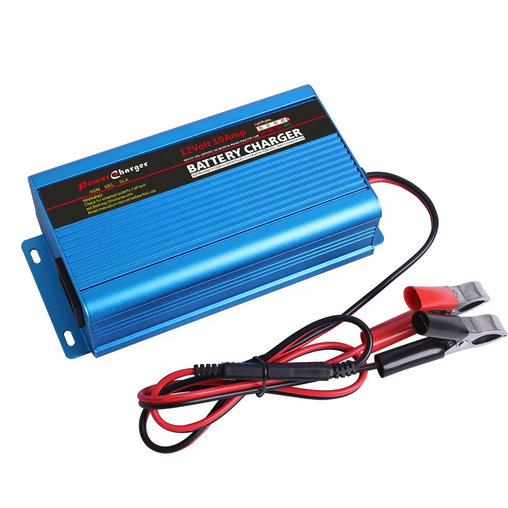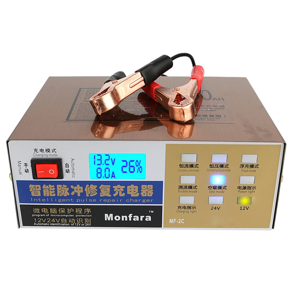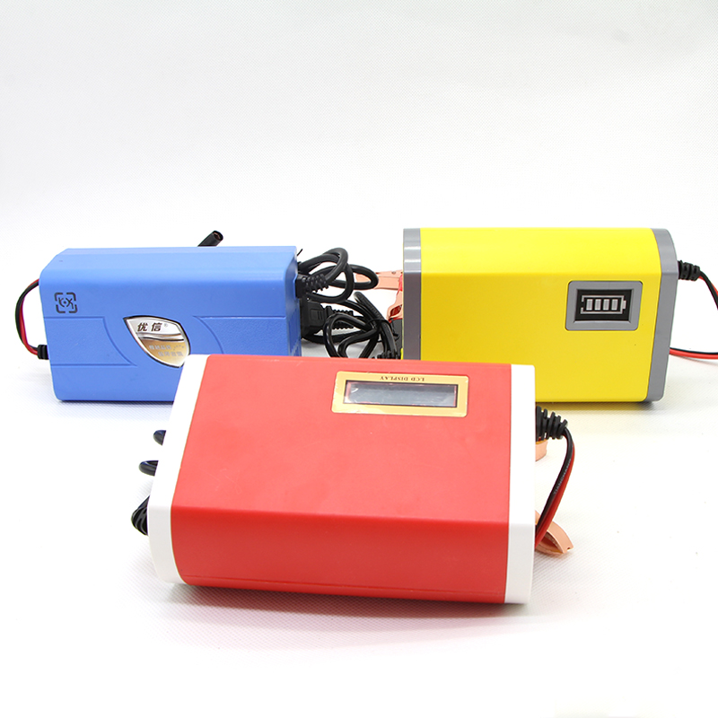

The output voltage of this voltage regulator is varied by varying the pot 10k which is connected to the adjust pin of LM317. The output voltage of this voltage regulator is variable from 1.2V to 37V and the maximum output current from this IC is 1.5A. This unregulated DC voltage is now applied to the LM317 variable voltage regulator to provide regulated DC voltage. Thus the output of the capacitor unregulated Dc voltage. The pulsating DC voltage is applied to the 470uF capacitor to remove the AC ripples. This process is also called as rectification. Here diodes D1, D2 are used to convert low AC voltage to pulsating DC voltage. The output of the transformer is connected to the Diodes D1, D2. The main supply voltage 230V, 50Hz is connected to the primary winding of the center tapped transformer to step down the voltage to 15-0-15V. This automatic battery charger circuit is mainly involves two sections – power supply section and load comparison section. Automatic 12v Battery Charger Circuit DiagramĪutomatic 12v Battery Charger Circuit Diagram Circuit Diagram of Automatic Battery Charger.I have kind of moved on from desulfators and have focused on how not to let a battery sulfate, as in, better battery chargers. There is a mountain of designs, information, personal experience, and success stories there, from around the world. Look for "Direct drive" and "voltage doubler". If you are interested in desulfator designs that actually work, go to the "lead Acid desulfator forum", ( ) under the "pulse charging and desulfation" section. The little inductive kickback circuits out there are a waste of time. It takes a lot of energy to convince sulfates to reform into sulfuric acid. These bogus circuits have done more to sully desulfator usage than to desulfate batteries. There are a huge number of desulfator circuits out there that are grossly under powered, producing less than 5 amps of pulse current. A $19 motorcycle battery from X-Mart is a waste of time. A battery that has sat in a shed to two years is a waste of time. The success rate varies based on battery size and construction, amount and age of sulfation, and power of the desulfator. Pulsed desulfation, where a battery is pulsed with high amperage pulses (>100 amps) will often bring a battery to a higher state of health. Failure to charge a battery correctly leads to sulfates building up and hardening on the plates and thus, early battery failure. They don't realize that a battery has to be charged is a specific way in order to maximize the conversion of sulfates back into sulfuric acid.

#BATTERY PULSE CHARGE CIRCUIT FOR USE WITH STANDARD CHARGER PLUS#
Too many people think of a lead acid battery as a big capacitor, in that all you have to do is replace the energy you used plus some extra. "Pulse conditioning" is a far better term for what is being done to the battery. "Pulse charging" is a very poor description because there is very little charging is going on.

Most of the so called "intelligent" chargers have a pulse charging mode, that applies to both nickel & lead chemistries - so far I've not bothered taking any measurements. The arrangement worked brilliantly with Ni-Cd cells, but the results with Ni-Mh were less impressive. The clamp rectifier was SB to limit the amplitude of the reverse excursions. The circuit was the basic capacitor input voltage doubling rectifier, the forward pass rectifier was the basic fast silicon so the Trr produced the required reverse spikes. In the end I used a capacitor coupling with a selected combination of fast silicon and Shottky-barrier rectifiers on the transformer output of a surplus SMPSU. Years ago I experimented with this, but found the results with 50Hz unimprssive. The same method applies to nickel chemistry, especially Ni-Cd. Putting a resistor in parallel with the half wave rectifier put a small reverse flow between each pulse of raw DC current. Originally for extending the life of zinc/carbon cells, it borrows from an electroplating technique of periodically reversing the current flow to get smooth even plating - just raw DC would plate some of the zinc back on the casing, but it was rough and granular. Click to expand.Pulse charging dates back to the 60s, the Dutch called it electrophoor.


 0 kommentar(er)
